Knot working!

Introduction

Knots are knots, but some are more suited to a particular purpose than others.

Sometimes the name gives this away.  A ‘bend’ is a knot to join two ropes.  A ‘hitch’ attaches a rope to an object, a ‘loop’ forms a (usually) fixed loop in a line, either free or around an object.  But many knots do not give this away in their name – Bowline, Reef knot, Figure-eight knot etc.

Often, the same knot may have different names (Reef knot/Square knot, Sheet bend/Becket bend etc.) depending on geographies and usage etc. Focus on application and method rather than name!

There are also often different ways to tie the same knot – we show two ways for the Sheet Bend and Bowline here for example – pick a method that works for you.  So long as the knot is tied right and has right intended use/purpose, there is no right method.

A common means of describing the various parts of a rope and certain shapes used to form knots is important.  We use the following:

Working end:  The part of the rope we are using to tie the knot (Might hear ‘tag end’ and ‘running end’ but avoid and try to use more universally accepted term)

Tail: The end of the working end (technically either end but we are generally working with the working tail so ‘tail’ usually refers to this)

Standing end:  The other end of the rope

Standing part:  The part of the rope between the standing end and the knot – this is the part of the rope that will likely be under tension once the knot is tied

Bight – a loop in a rope (not knotted or fixed)

An overhand loop – if the tail of a bight is passed over the standing end, you get an overhand or anti-clockwise loop

An underhand loop – if the tail of a bight is passed under the standing end, you get an underhand or clockwise loop

Anchor point – not necessarily an anchor but just the object you are tying to.

You might hear Bitter end, particularly in a boating context.  This is the end typically attached to the boat (Derivation: A bitt is\was deck furniture like a cleat).  Some people refer to the tail end as the bitter end but this is incorrect.  Try to avoid this term as it is not universally known.  A bitter end is also the standing end – use that instead.

Rope Terminology – helpful video: https://www.youtube.com/watch?v=Yn0JYAnPKlQ

 When teaching knots to others, ‘show and tell’ at same time.  Use precise, succinct language, always teach checkpoints! 

(Ideally all knots should follow a set tying pattern of ‘right to left, up then down’ as it makes the knot easier to verify by someone else but this is usually beyond novices and many right-handers will prefer to tie left to right – for example doing turns)

The following knots are useful for mariners (especially Powerboat 2 students!)

  • Reef knot 
  • Clove Hitch
  • Round turn and two half hitches
  • Bowline
  • Sheet Bend

Reef knot

Description: Thought of as a knot (i.e. bend) for joining two ropes of equal diameter.  (However more accurately it is a binding knot for securing items rather than a bend for joining ropes – see ‘Disadvantages’, below)

Advantages: Simple to tie – most people already know this knot!  Easy to recognise if correctly tied.  Easy to untie if not jammed.

Disadvantages: Can slip and invert easily under (heavy) load.  Can jam and be hard to untie.  Not effective if ropes are not same diameter – use Sheet Bend instead.  Mis-tying the reef knot can end up in one of three knots that are significantly weaker than even the reef knot!

Tying Steps

  1. Hold the two ropes, one in each hand, tails pointing to each other
  2. Form a diagonal cross with 10 cm or so in from the tails with the right tail over the left tail
  3. Take the right tail under the standing part of the left rope
  4. The same tail, which is now on the left pass over and under the other tail
  5. Tighten (‘dress and stress’) all parts up

Note: This knot is easier to tie than to describe!  Think: ‘Right over left, left over right

(It can be made more secure by having 15cm tails that you then tie an overhand safety knot in but there are better bends to use instead – Alpine Butterfly Bend, Zeppelin Bend, Double Sheet Bend etc.)

Fun fact:  Europeans tend to tie their shoes with a ‘doubly slipped reef knot’ (Americans often use twin looped bunny ears or ‘two-loop shoelace knot’).

Checkpoints

  1. Two over-locking bights (see picture 1)
  2. The tails are either both on top or both below the two standing parts (i.e. they oppose each other) (see picture 1)

Picture 1 Credit: www.cavinguk.co.uk

Mis-tying the reef knot can end up with either a thief knot, a granny knot or a grief knot – all likely to fail under little load (picture 2, thief, reef, granny, grief l-to-r)

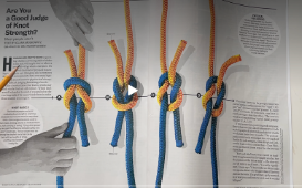
Picture 2 Credit: Scientific America March 2025


Untying

If not jammed, easy to untie.  Unload and either ‘unpick’ from one tail or push the two bights apart by grabbing respective tails/standing ends in each hand and push hands together.  If jammed under heavy load may find unable to untie.

Clove Hitch

Description: Hitch to (temporarily) secure a rope to a post, spar, or carabiner

Advantages: Can adjust easily when tied so great for fenders when you need to adjust height.

Disadvantages: It can slip if the rope is stiff or if there is not enough friction. It should not be used as a permanent, high-load securing, particularly on slick surfaces.

Tying: Easy to tie. (there is a variant if struggling to tuck tail back.)

Method 1 :Traditional approach

Steps

  1. Wrap: Pass the rope around the post.
  2. Cross: Bring the rope over itself, forming an ‘X’, and wrap it around the post again.
  3. Tuck: Pass the working end under the second wrap (the last turn).
  4. Tighten (‘dress and stress’): Pull both ends to secure the knot.

Nice demo: https://www.youtube.com/watch?v=JMc7ejuBabk

Checkpoints

  1. Two turns (technically: ‘one round turn’) around anchor point
  2. Diagonal locking ‘bar’
  3. Working end and standing end are in middle of knot

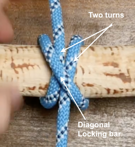
Picture 3 Credit: @jasonknots (YouTube)

Untying

Easy to un-tie.

 Method 2: Front loop

  1. Demoed in this video – can ignore the safety two half hitches at the end – just focus on tying method: https://www.youtube.com/watch?v=jSElk0LenR4

Round Turn & Two Half Hitches

Description: a hitch to fasten a rope to a post, ring, or spar – e.g.  for mooring boats or attaching fenders

Advantages: Excellent under load (friction from the initial turn allows it to be tightened without binding). Usually easy to untie even after holding heavy tension. Can be untied under load.

Disadvantages: In extreme situations can jam or slip (esp. with slippy ropes like Dyneema) but this is fairly rare.

Tying Steps:

  1. Round Turn: Wrap the working end of the rope around a post or ring twice, ensuring the wraps sit neatly (ideally right to left so that ‘figure 4’ memory trick below works).
  2. First Half Hitch: Bring the working end around the standing line (the main rope) and pass it through the loop created, then pull tight. “Figure 4 then back through the back door”
  3. Second Half Hitch: Repeat the process of passing the working end around the standing line to create a second, identical hitch.
  4. Finish: Pull the entire knot tight, ensuring the half hitches are secure against the main line

Notes:

A good way to remember the half-hitch is ““Figure 4 then back through back door”.

Bring the tail of the working end in front of the standing part down and then at right angles to form a shape that looks like a figure ‘4’, then pass the tail around the back and through the loop created by the ‘4’.  See Demo of “Figure 4 then back through the back door”.  (Only works is you wrap the turn right to left, otherwise it’s a ‘figure 4’ seen from behind!). https://www.youtube.com/watch?v=jSElk0LenR4  (from 0:40 seconds in)

Fun fact: The two half hitches form a clove hitch if done correctly. If done symmetrically, it’s technically a round turn and cow hitch which is not as secure but in practice should not be an issue.

Checkpoints

  1. A ‘full round turn’ (this looks like two turns on the anchor point)
  2. Two cinched up half hitches (important) that go in same direction, not symmetrical (last bit less important)

Picture 4 Credit: knots3d.com

Untying

Can be untied under load!  Uncinch half hitches which should not be under tension, slip the round turn when ready.


Bowline

Description: Fixed loop knot, used a lot on boats esp. for mooring etc.

Advantages: Strong(-ish), Can be pre-tied loop or tied around object easily, easy to check proper tying (but only if you know what to look for – see checkpoints, below)

Disadvantages: Like reef knot can work loose under repeated load/unload situations.  OK as a ‘marine rescue knot’ (MOB etc.), but would not be regarded as safe for rescue on land.  High risk of failure if tied incorrectly.

Tying: Trad method is ‘Bunny’ or ‘Snake’.  Arguably better is ‘Snap’ or ‘Jedi’ method.

Method 1 :Bunny

Steps

  1. Form a small overhand/anti-clockwise loop. (Good to use both terms when teaching as some people struggle to understand one, but better understand the other).

(Note that the size (diameter) of the eventual loop that you form will be half the rope left on the working end the other side of the small loop, less 10-15cm! You cannot (easily) adjust size of standard Bowline loop when tied)

  1. Pass the tail of the working end up through the loop (‘Bunny out of his hole/burrow’)
  2. Pass the tail around the back of the standing part anti-clockwise (‘Bunny behind the tree’)
  3. Feed the tail back down the loop (Back down the hole/burrow’)
  4. Make sure you have at least 10, ideally 15cm tail – 10cm is about width of male fist, 1.5 female fist, YMMV: measure it!
  5. To tighten (or ‘dress and stress’), hold tail and inside of righthand loop in one hand, standing end in other and pull together

Checkpoints

  1. A bight behind the standing part of the rope (some say looks like a lifejacket)
  2. Held in place by a locking ‘collar’ against the tail and one side of the loop.

Picture 5 Credit: @dappersapper (Youtube)

Note: The tail should be inside the loop for a std bowline.  If the tail runs in the same direction as loop but outside you have tied a Dutch/Cowboy Bowline – ignore myths this is weaker – indeed it is proven that it stronger if the loop is sideways loaded! But you should know what you have done (bunny went clockwise behind tree instead of anti-clockwise.)

Untying

Cannot be (easily) untied under load – don’t try.  When unloaded, ‘Crack the bight’: Turn knot over so bight runs over, not under, the standing part.  Push centre of bight towards standing end.  Knot will loosen with ease irrespective of prior loading.  Pull tail back, knot will unravel.

Method 2: ‘Snap’ or ‘Jedi’

 Arguably better than Bunny for several reasons: 

  1. Some feel easier to remember
  2. You can pre-tie half of it so that when you arrive at a pile, mooring ring etc. you simply need to pass the tail round/through the object and then through the pre-formed slipknot
  3. Because people almost always learn Bunny with the fixed loop towards them, some people (not all) really struggle to tie it when they need the loop to be away from them (i.e. the loop is inverted so Bunny needs to dive down burrow first – not intuitive!)
  4. The method demonstrates that the bowline and the sheet bend are the same knot: if you know how to tie one this way, you know how to tie the other – you get a ‘toofer’!

Steps

  1. Form a small overhand/anti-clockwise loop. (Good to use both terms when teaching as some people struggle to understand one, but better understand the other).

(Note that the size (diameter) of the loop that you form will be half the rope left on the working end, less 10-15cm! You cannot (easily) adjust size of standard Bowline loop when tied)

  1. ‘Collapse’ or fold the loop back onto the standing end
  2. Pull a bight from the standing end through this loop. (If you cinched this down it would be a standard slipknot – but at this stage don’t)
  3. Take the tail and pass it up (under to top) through the slipknot loop
  4. To tighten (‘dress and stress’) – Hold right hand side of loop and with plenty of tail (10-15cm) in one hand and the standing end in the other and pull – the knot will ‘collapse’ into a standard bowline

Note this method must be demonstrated as first time it feels a bit less intuitive than Bunny.

Checkpoints

Same as Bunny

Untying

Same as Bunny

Note:

Most Youtube videos for Snap/Jedi Bowline show a slightly different approach in step 1 and 2 by first doing an underhand loop and then passing the bight through – it’s the same result just slightly different technique.  The advantage of using the method above is the loop direction is the same as in Bunny so you can ‘fail-over’ from one method to the other more easily.

If in step 4 you pass the tail down through the loop (top to bottom) you form a Cowboy/Dutch bowline!

Relation to sheet bend:

If you tie the slipknot in the cordage/rope that is the smaller diameter, and then pass the second thicker cordage/rope through the slipknot loop, and pull holding the standing end and tail of the thicker cordage and standing of the thinner cordage, it will collapse into a sheet bend proving they are the same knot.


Sheet Bend

Description: Bend for joining two ropes, especially good if different diameters.

Advantages: Easy to tie, low profile, more secure than Reef Knot

Disadvantages: Requires constant load, can be mis-tied, Can slip with slippy rope – Double Sheet Bend is option in these cases.

Tying: Trad method, Snap/Jedi method (arguably preferred)

Method 1 :Traditional

Steps

  1. Create a Bight:Make a U-shaped bend (bight) in the thicker or more rigid rope.
  2. Pass Through:Pass the working end of the thinner rope up through the bight.
  3. Wrap Around:Wrap the thinner rope around both legs of the bight, going behind them.
  4. Tuck Under:Pass the end of the thinner rope under its own standing part.
  5. Tighten:Pull all four ends to tighten and “dress and stress” the knot.

Note: Can be used for equal diameter rope too and will be more secure than Reef Knot

Checkpoints

  1. Bight is in thicker rope/cordage
  2. Loop formed by thinner cordage locks down on tail (unlike Reef knot which is symmetrical)

Picture 6 Credit: Paracordplanet.com

Untying

Hard to untie under tension but like the Bowline, once unloaded, you can ‘Crack the bight’ pushing either bight back to the standing end of the other rope. 

Method 2: ‘Snap’ or ‘Jedi’

 Arguably better than Traditional method for several reasons: 

  1. Some feel easier to remember
  2. The method demonstrates that the bowline and the sheet bend are the same knot: if you know how to tie one this way, you know how to tie the other – you get a ‘toofer’!

Steps

  1. In the thinner rope/cordage, form a small overhand/anti-clockwise loop. (Good to use both terms when teaching as some people struggle to understand one, but better understand the other).
  2. ‘Collapse’ or fold the loop back onto the standing end
  3. Pull a bight from the standing end through this loop. (If you cinched this down it would be a standard slipknot – but at this stage don’t)
  4. Take the tail of the thicker rope and pass it up (under to top) through the slipknot loop
  5. To tighten (‘dress and stress’) Pull both ends (standing part & working tail) of thicker cordage

Checkpoints

Same as Traditional

Untying

Same as Traditonal

Relation to Bowline:

The Sheet Bend is the bend version of the Bowline, you can confirm this by comparing the knot element of both.


Home-made Internet-controlled Irrigation Valves

“Timer-based Irrigation Valves with Internet Control.”

This is the latest variant of a project I started last year which used a Raspberry Pi and Homekit bridge software to control greenhouse irrigation.  The solution worked well, but the software was a clever adaptation of a Java-based HomeKit bridge developed by a colleague.  In essence – way above my technical pay-grade.  

This year I fancied adding another bank of valves, so looked around for a means to do this myself!

I happened upon the Sonoff 4CH Pro R2.  This nifty device basically has 4 independently controllable latching relays, Wifi connectivity, phone app control and can be AC Mains or 5-12V DC powered.

Of particularly note about the Sonoff range is that they are based on the ESP2866 chip and that there is a strong community behind an alternative firmware called Tasmota and the Sonoff devices either directly support the ‘DIY’ flashing of the firmware or they are pretty hackable – depending on the device.

Tasmota provides extensive support for controlling the devices over various protocols including MQTT and offers great integration capabilities to Home Automation solutions such as OpenHAB which has been ‘on the list’ of things to do…

Step 1 though, as described in this post, was to get the valves up and running using the Sonoff app.

The Sonoff 4CH Pro R2


The Bill of Materials

This is not a particular cheap build – but something with the same capability available commercially such as the Gardena Watering Valve Box V3, with three solenoid valves would set you back about GBP 200-250 – without timer or connectivity.

A commercial alternative: Gardena enclosure and valves

This is what I used:

Sonoff 4Ch Pro R2 as above- the Pro is needed as it has the 12DC input (as well as 433 radio control as an added extra..)

Some Cat 5 cable for connecting the Sonoff enclosure to Valve enclosure

2 enclosures – one  for the Sonoff and   one  for the Valve enclosure. Note: these boxes are IP55, which is ‘low pressure jets from all angles’.  If you want something more robust weather-wise, go for a IPx6.  (The enclosure for the Sonoff is *just* too small internally because of the screw mounts.  It means trimming the corners of the Sonoff – it does have mounting lugs so space to do this but if you don’t want to do that, source a bigger enclosure)

3 12V Solenoid Valves – these seem great value at under GBP 14 each

4 Garden Hose Tap adapters – best to get as good quality as you can.  Mine were pretty budget.

Plastic piping:  1 x BLK PP Plug Thread 1/2 (SKU 350390), 3 x BLK PP Tee Thread 1/2 (SKU 350268), 3 x BLK PP Nipple Thread 1/2 (SKU 350299), 4 x BLK PP Reducing Socket M x F Thread 3/4″ x 1/2 (SKU 350341) – all from here.  (Pipestock’s postage charge is quite chunky but the service and speed of delivery is very good).

An old 12VDC 2A wall wart I had kicking around (mine had a 90 degree connector – this may be important for clearance in the enclosure if you go for the same enclosure I did)

A rough total cost including shipping, where applicable, would be about GBP 110-115.


The Build

The ‘plumbing’ part is pretty straight-forward.

The approach I found to work well was to create three sub-assemblies of the Solenoids pairing each with a T-connector and reducing connector:

The valve ‘sub-assemblies’

Your valves are likely to be ‘one-way’ – you may see a flow arrow on the underside of the solenoid or check the spec – the site I got mine from had the spec in PDF form.  Make sure everything is (water) tight and use teflon tape if so inclined.

When the valves are joined you will not find it easy to tighten the sub-assemblies further.

Now join the sub-assemblies with the parts curiously called the threaded nipples, together with the threaded plug one end and another reducing part the other:

Now would be a good time to do a leak test:

Worth running at as much pressure as you can to test


Drilling the enclosure requires some skilful measurement – it’s tempting to use the cut-outs as a guide but they are not an exact spacing in relation to the valve assembly – or at least in my combination that is what I found.  Use one cut-out as the starting point and measure the other two.  Measure for the inlet and drill.  (I used a flat wood bit because that’s what I had.  You have the choice of using a 22mm in which case you may need to sand out the cutouts by a half mill or so or use a 25mm and accept a you will have a ‘gap’ around the valve threads on exit.  I did the ‘hard’ or rather time-consuming way – using a 22mm drill bit).

You should have something like this:

Drilled enclosure

You now need to ‘wrangle’ the solenoid valve assembly inside the enclosure (having first removed the hose tap connectors you may have used for the leak test).  Fortunately, there is a lot of flex in the enclosure (at least the one I used).  With the hose connectors attached the valve assembly is ‘secured’ within the enclosure.  You could provide additional support to the assembly if you wish.  It seems fine without….

Now for the wiring.  I spade-terminated a length of cable for the +ve supply of each solenoid and ran that to a connector strip.  The -ve connection I just daisy-chained to each solenoid and also back into the connector strip.

Then whatever length of cat5 you want (from one enclosure to the other).  I doubled the twisted pairs so three pairs are supply to respective solenoids and the forth pair is common. 

I ran the cat5 out through a drilled hole for expediency.  Ultimately some panel mount and wired IP68 4 pin connectors like these would be a nice touch but I didn’t have the time to order them….


Finally, the Sonoff unit is installed in the second enclosure.  Annoyingly, the internal measurements of the enclosure weren’t available and it meant trimming the corners of the Sonoff with a multi-tool.  Not a problem for me but you may want to source a bigger enclosure if it bothers you doing this.

The relays on the Sonoff do not supply power, so you basically need to have power going to the ‘com’ tab of each relay and then each solenoid wired to a respective normally open tab of a relay.  Thus when the relay is closed, 12V flows to the solenoid.  

There is probably a much  more elegant way to wire this but essentially I cut the connector off the wall wart 12V supply and put both ends (+ve and -ve) into a connector block.  I connected +ve to each of the ‘common’ tabs of three of the relays.  So essentially 12V power goes to each terminal and also powers the Sonoff through the 12VDC input.

 Then I wired the NO (normally open) terminal of three of the relays to the three pairs of cat 5 that correspond to the +ve supply of each of the solenoids.

I’m not sure this dodgy ‘circuit diagram’ helps but you’ll figure it out…:

OK – it’s not pretty or clever but I’m powering the sonoff and the three common tabs of three relays with 12V

The App

The Sonoff ‘comes’ with iPhone and Android app support – the ‘ewelink’ app.  It’s OK … in that it’s not rubbish and it works reliably.  You can set schedules and see status of the relays:


The Result

Works as expected!  Reliable. No leakage.

Liked it so much I built 2.


The Future

There is more to come hopefully.

First, flash the firmware with Tasmota.  This offers some connectivity benefits to OpenHAB which I plan to implement, and would give HomeKit integration and decent rules-based behaviour and data capture and monitoring.  

Add some sensors.  With Tasmota, the Sonoff’s I2C pins can be exploited for sensors.  I’ve got some DS18B20 2 wire temperature sensors.  I plan to get some I2C moisture sensors too.  Maybe also some rain sensors.

That way, the solution can provide feedback on actual moisture levels and I can automate the schedules based on this, and with the outside unit, compensate for wet days.

Probably also plan to build one or two additional units for the ‘top garden’!

My version of the Arduino-based Turntable Tacho


My version of the Arduino-based Turntable Tacho

My Tacho keeping the LP12 honest


“This is based on a diyAudio project, with some little tweaks of my own.”

There is a thread over on diyAudio that’s a few years old but still very popular.  Some folks figured out how to use an Arduino Uno with a sensor to accurately measure the rotational speed of a Turntable.  

Maybe if you’ve got a modern TT or a model renown for rock-solid speed and low wow & flutter then this is of no interest.  But some of us have, well, older machines.

It’s really very simple – the hard work (the software or ‘sketch’) has been done for you, and it’s basically about connecting power to the Arduino, wiring up the sensor and positioning it. 

You may not be surprised that I’ve built a few iterations of these for a couple of reasons!

First, my Linn Sondek LP12 is over 30 years old and is belt-driven, with an AC motor and a (reasonably) simple power supply driving the motor.  (known as the ‘Valhalla’ power supply – essentially an AC regenerator). The rotational speed is adjustable – by mechanically orientating the motor spindle off the vertical by lighting or loosening a couple of retaining screws (!).  Second, I’m part-way through (!) building another diyAudio project – a  multi-phase sine-wave generator that has much more flexibility than the Valhalla (including voltage supply and phase offset), but which doesn’t have a speed feedback loop, so manually knowing the RPM is useful.  Finally, I have a couple of other TTs – 2 Linn Axis in fact that I plan to eBay but which need servicing – These have potentiometer speed control but are also not rock-steady all the time.

The prototypes..

So, I build the original project on an Uno per the thread and just used a breadboard to connect sensor to board, power etc.  Checked the speed – all worked great.  I used the IR obstacle avoidance sensor which is a pretty ubiquitous Arduino sensor board but the Hall effect sensor, that measures when a magnet passes past, is another option.  To make the sensor work, I used some 3M reflective tape on the side of the turntable outer platter.  

However, perhaps because the Axis platters are a bit shinier, the IR sensor wouldn’t work for them.  And it wasn’t very portable, given I hadn’t boxed it in an enclosure.

That got me thinking.  I could i) use a Nano so I could box it in a smaller form-factor, ii) change the display for a little OLED for the same reason.  Finally, iii) make it so I could use one of two sensors, depending on TT – so have a Hall effect sensor as well as the IR sensor  just for good measure.  (a tiny magnet, blu-tacked to the platter switches the sensor in this case).

I made a couple of changes to the original sketch to accomodate the different PINs on the Nano and the OLED  display.  I powered the Nano with a 9V PP3 (which you might know as a 1604x) since the Nano has a Vin and on-board regulator that can handle up to 12Vs.  Given the device would only be used for a minute or so at a time, I wasn’t too concerned about power consumption.

It worked out pretty OK – in that it worked.  

I housed it in a little metal project box.  Frankly, a too small project box really, it was a bit of a messy cram.  I had a small issue cutting the screen opening (originally I did it for a 128×64 OLED, but actually used a 128×32 one) and stupidly glued the screen and PET/perspex screen ‘cover’ I used from recycling some packaging by using – Superglue.  

End result was the glue reacted with the PET or Perspex and it ended up cloudy.  

Usable – but ugly.

The best bit was the off-board sensors, boxed in little cases, connected by a cable with 2.5mm plugs.


The ‘final’ iteration

It struck me that I could house the ‘works’ in a slightly bigger enclosure, include the different types of sensor, which could be switched between them and still have it ‘handheld’.

So, the bill of materials was as follows:

  Enclosure,  Arduino Nano,  SPST on/off mini rocker switch,   mini rocker (on-off-on), IR sensor, Hall effect sensor,  OLED screen,  NeoDymium Magnet

The on-off-on will switch the sensor signal to the Arduino.  Rock left, and the left sensor is activated (The reflective sensor in my case).  Rock right and the right sensor is activated. They are obviously never both active at the same time.  (If you chose to do this, just remember the switch pins will likely be opposed – use a continuity check if in doubt!).

(I initially shared the signal wire and switched the 5V supply.  The Hall effect sensor was fine with this but the IR sensor didn’t like it at all.  Not sure why, possibly to do with the fact the signal cable is pulled high and the program measures HIGH to LOW transitions – but essentially above my technical pay grade). Wiring it the way I have done has the disadvantage that you are powering both sensors all of the time but my ‘on’ time is always less than a couple of minutes, so no real issue)

They will share the same signal (and ground) cable.

A rough layout of the components helps work out connector lengths etc.

The software firmware/sketch includes a provision to calibrate the actual value seen from the output of the crystal rather than assuming the ‘spec value’. I’d not done this on previous iterations – basically because I didn’t have a frequency counter.  But now I do,  so….  worth a quick  check…

….. and at 15,630.60 Hz it was adrift from the theoretical 15,625 by about … 0.04% – so  not too significant but worth dong if you can.

(Said another way, instead of reading 33.333 as you see in the picture, the uncalibrated sketch would have calculated 33.321)

While I modified the sketch for the OLED display from the original PCF8574 LCD library and otherwise hacked about with it by commenting out pieces I didn’t need – If you are minded to make one and are looking for the sketch, I later found somebody else had done something very similar but with tidier code so you’re better off going here for it.

Marked out on the enclosure the display and switches and then used the old, time consuming, ‘drill many holes and file’ approach to making good…


The bits and pieces for the new version
Rough component layout
Calibrating the SW from the actual crystal frequency (Optional step!)


Enclosure mark-out
Some (many) minutes later..


Pretty much got as good as I thought was possible by hand… fairly pleased….


Connect the dots…


Connected the connecting wires.. and that’s basically it.


The result

Per the initial picture, it works excellently…

The turntable now runs at 33 and 1/3 with 180g Vinyl and needle down (it runs slightly faster needle up no record on – 33.35).

The output is consistent irrespective of which sensor – IR reflective or Hall effect, is used.  (To use the Hall effect, I blu-tacked a really small Neo-Dymium magnet to the platter side.  For the IR reflective (obstacle) sensor, I taped  a small 3M self adhesive reflective strip to the platter side.


Re-conditioning an original 1950’s Tannoy 12 inch Silver Monitor Canterbury

Re-conditioning an original 1950’s Tannoy 12 inch Silver Monitor Canterbury


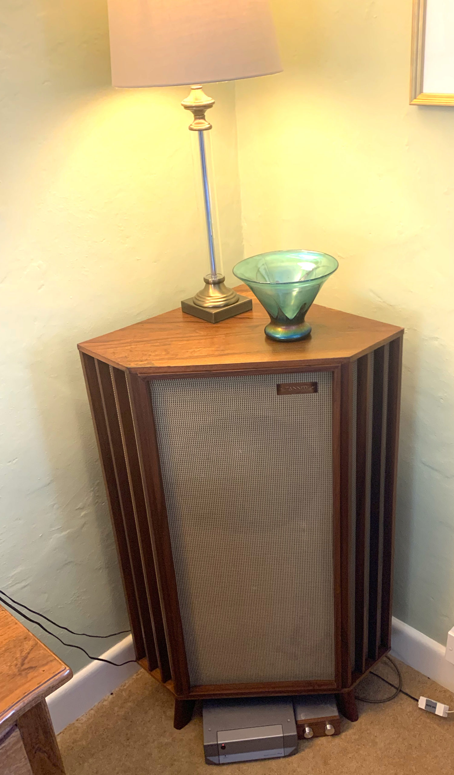
Tannoy 12″ Silver monitor in Canterbury Enclosure


“This was intended as a quick ‘spruce-up’ of an original but tired Tannoy speaker – it took a bit longer than expected and isn’t perfect but I was pleased with the results”.

If you’re interested in vintage Hi Fi then you’ve likely heard of Tannoy’s original range of concentric speakers.  If you’d like to know more – have a look here.

The concentric design incorporates the tweeter cone inside the centre of the base unit and is still widely used today for studio monitors.

This range of original speakers – even ‘naked’ without cabinets, now command eye-watering prices (well in excess of £2K for example) ….  and …. my father-in-law had one stashed away in his garage!

He’d bought it new, but was lucky enough to get it for a knock-down price when Cole Brothers of Sheffield were shutting down their audio department some time in the late 50’s or early 60’s.

For anyone that’s interested, it’s marked LSU/HF/12/L which is the 12 inch silver monitor, regarded by many as their best (well the 15 inch one is at least).  The driver serial number is 023941 and it’s cabinet 549.

Since it was very definitely languishing away, I offered to ‘fettle’ it so we could eBay it and he could have a useful pot of money for a holiday etc.

My objective was to do a light, sympathetic improvement – I didn’t want to overdo it as some purists might consider that to reduce the value (that’s an excuse for otherwise saying I’m not a furniture restorer by any stretch of the imagination!)

Half the promise is now fulfilled.  (I still have it in my living room since he was keen that someone in the family got some use out of it.  When it’s fully broken in (!) I’ll get it sold – for now I’m enjoying it!

The starting point

The cabinet’s lacquer was distressed, there were a few dark ring marks from mugs being left on top, a few chips to the veneer and the grills were pretty filthy.


The ‘restore’

I rubbed the unit down with wire wool, artificial wire wool (3M) pads and various grades of wet n dry.

In some places I used spirit and a razor blade.  The lacquer was caked on!

The task was made much harder by the fact the grill (a plasticised type of cloth weave) was not removeable – at least I couldn’t see how without totally taking the unit apart.  Each quartered side has grilled panels separated by a small wooden detail – quite tricky.

I suppose all told I put about 30-35 hours into it over a period of a couple of weeks!

I found some veneer samples on the ‘bay.  In some places such as the end corner, the match is excellent – in others it’s still pretty noticeable (in some part due to my very basic veneering skills no doubt!) but at the very least I have protected the surface.

I had a decent amount of success with the dark marks and rings using propriety ring remover (which I suspect is just Oxalic Acid).

I then looked for an oil that had more oil than varnish – a Danish Oil and slapped that on.  I followed it up with Renaissance Micro Crystalline Wax – this is great stuff and I’d used it previously to give my Linn LP12 a really nice finish and I’ve used it on metal too – a proper conservator’s tool!

The grill cleaned up somewhat but as you can see not perfectly.


(The paper-y thing is actually the original paper Tannoy label, attached by screw to the rear!)


The Result – Part 1

The next problem was how to hook it up!

Being a single speaker (and back in the day they were rarely sold in pairs as this pretty much pre-dated Stereo),  I needed a mono amp. So…. I went on the ‘bay and bought a Cyrus Smartpower Plus Mono/Stereo amp.  ‘Course, this is a power amp so I also needed a pre-amp.  I thought this would be a good time to experiment with a passive pre.

Basically, there are a band of Hi Fi aficionados who swear blind about passives.  

In essence, (and being no expert) a ‘pre-amplifer’ is pretty much a misnomer anyway – for the most part the volume knob on a pre-amp actually attenuates, rather than adds gain.  So a passive pre-amp usually has some input selector and and some form of potentiometer to actuate the line-level signal.  No power required.

An active pre-amp by contrast can add gain, provide fancy (remotely) relay-switched inputs and can provide a preamp buffer which (as I understand it) can be useful to match impedances when the source and the output might otherwise be incompatible.


So, I bought a Tisbury Mini Passive Pre-amp!

As an experiment, I tried it in my main Hi Fi rig – replacing the active Roksan Caspian M1 Pre-amplifier.  I’d recently bought this (guess where!) but back in the day (2010s etc.) this retailed for over £1,500…. Not cheap.

I don’t want to start an active/passive war but I *think* I preferred the passive!!  However, I’d bought the passive for a purpose, and for me, part of the Hi Fi set-up I have is pure aesthetics – I love the Roksan Caspian’s rack look (strangely many don’t!).  So the Caspian is a keeper!

So, the way the Tannoy is wired up is:  FLAC (lossless) -encoded music is Roon-served to a Chromecast Audio, into the passive, and into the Cyrus, set on mono mode, powering the single Tannoy.

It sounded really good in fact.   Really ‘warm’ but still distinct.  Great range from high to low frequencies so I was very happy!

The Crossover

Of course, over the next few weeks, it didn’t stop me wondering about the speaker’s crossover..

Crossovers have capacitors and capacitors don’t last for ever.

So I thought I’d have a closer look.

It’s pretty simple.  What’s interesting is the custom two cap configuration in a metal enclosure.  

I also found the circuit diagram online:

So I decided to build a replica. I ordered a bunch of parts – including some Hi Fi-spec’ed (and priced) jumbo caps and induction coil of the correct values.


It looks pretty good assembled!

So I unmounted the original and replaced it with mine – using all original screw holes etc. to preserve as much originality as possible:


I decided to check the caps with my cheapo ESR meter (and sound like I know what I’m doing at the same time).  One was good, the other not.


The Result – Part 2

In a word – amazing!  Clearer, more defined.  A really great speaker – just wish I had two, and that it was actually mine!

It’s currently in the corner of my living room, and I can stream all my music via Roon.


The clarity and richness of the sound has made me want to find a way to stream my Vinyl from my Linn Turntable to it too – but that might be another ‘project’!


Battery powering the Muffsy Phono Stage


Battery powering the Muffsy Phono Stage

The Muffsy Phono Stage – Before

“There is nothing clever about this, but it’s effective and is even quieter than the already quiet adapter & on-board AC/DC power supply powered version.”

If you haven’t heard of the Muffsy Phono Stage you should check it out  here .  In essence, it’s a kit option of an open source phono stage design – the CNC Phono Stage that has a pretty wide following in the diy audio community such as  on Audiokarma.org   for example.  The CNC itself is based on some application notes from National Semiconductor for the LME49720 op amp.

Anyway, the nice things about the Muffsy version are – i) It’s a full kit minus AC Adapter  & Case, ii) specifically designed to fit in a nice, small, cheap case readily available online (the 0905), and iii) has great build instructions and support, if you need it, from from the enthusiast behind ‘Muffsy’. 

It a bit of fairly simple soldering and you end up with a quality phono stage.  Anyway I built one (and then a couple more as it happens).  

The phono stage is powered by a separate AC-DC low ripple power supply, which fits in the same box.  

I had a few issues with hum initially (which is how I know the support is so good), but it sounded great.  

I also have a   Rothwell Rialto phono stage  which retails for about £400 and which HiFi Choice magazine said  a few years ago: “This unit sounds utterly sublime.”  

To my ears, both are frankly great, but if the Rothwell has the edge, it sounds ever so slightly quieter. ( less hiss, needle up, same photo stage gain, same pre-amp settings)

So – why not see if powering the Muffsy by battery makes any difference – why not indeed!

There is going to be two parts to this – modifying the phono stage and building the battery box.

The Phono Stage

The phono stage has an AC socket and a single way switch, and a separate board for the PSU.  Out comes the AC socket, switch and power supply.

Because the phono stage requires a +v/0v/-v dual rail supply, we’re going to feed the phono stage with a shielded three core cable and use a DPST switch on entry (to ensure both + & – voltages can be cut).  Then we need to fab a three core cable for inside the enclosure.  I decided to braid 22awg wire, and cover in a copper shield, tied to 0v, just for good measure.

One of the cool things about the Muffsy Phono Stage is the backplate, designed for the 0905 enclosure. I wanted to reuse this so I needed my new DPST switch and my dual rail DC supply to fit in the pre-cut holes.  No problem with the SPST round rocker – there is a DSPT  version  of the same thing.  For the 12mm power socket – I found   GX12  ‘aviation plugs’.  Genius, and they look good too.

Apologies for the lighting but hopefully you get the gist.  The GX12 in the backplate bottom left presents 3 wires – +12v/0v/-12V.  Common (blue) goes straight to the choco block at the rear of the case, red and black go via the DPST switch to same.  The cable is routed as far away from any signal paths as possible, and is shielded.

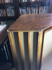
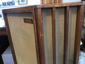
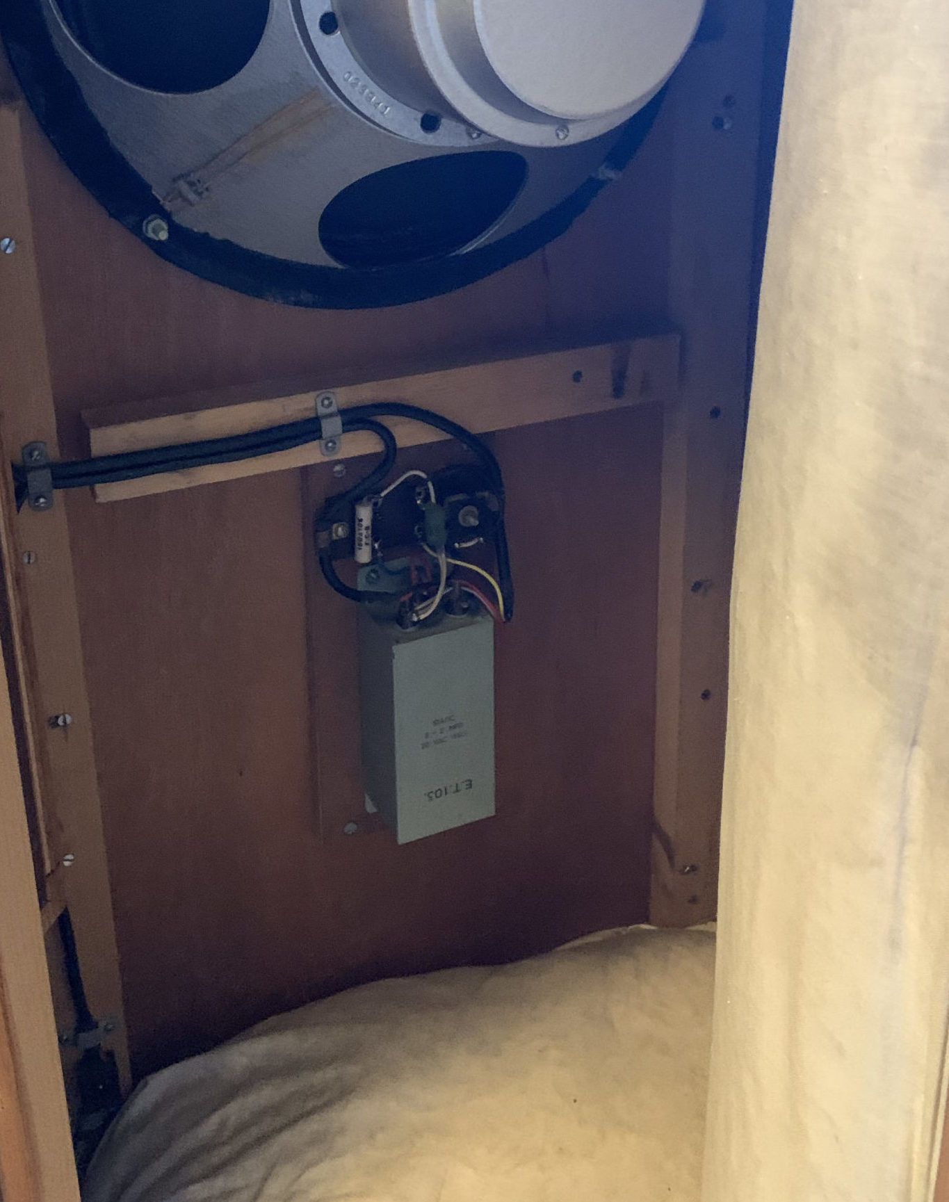
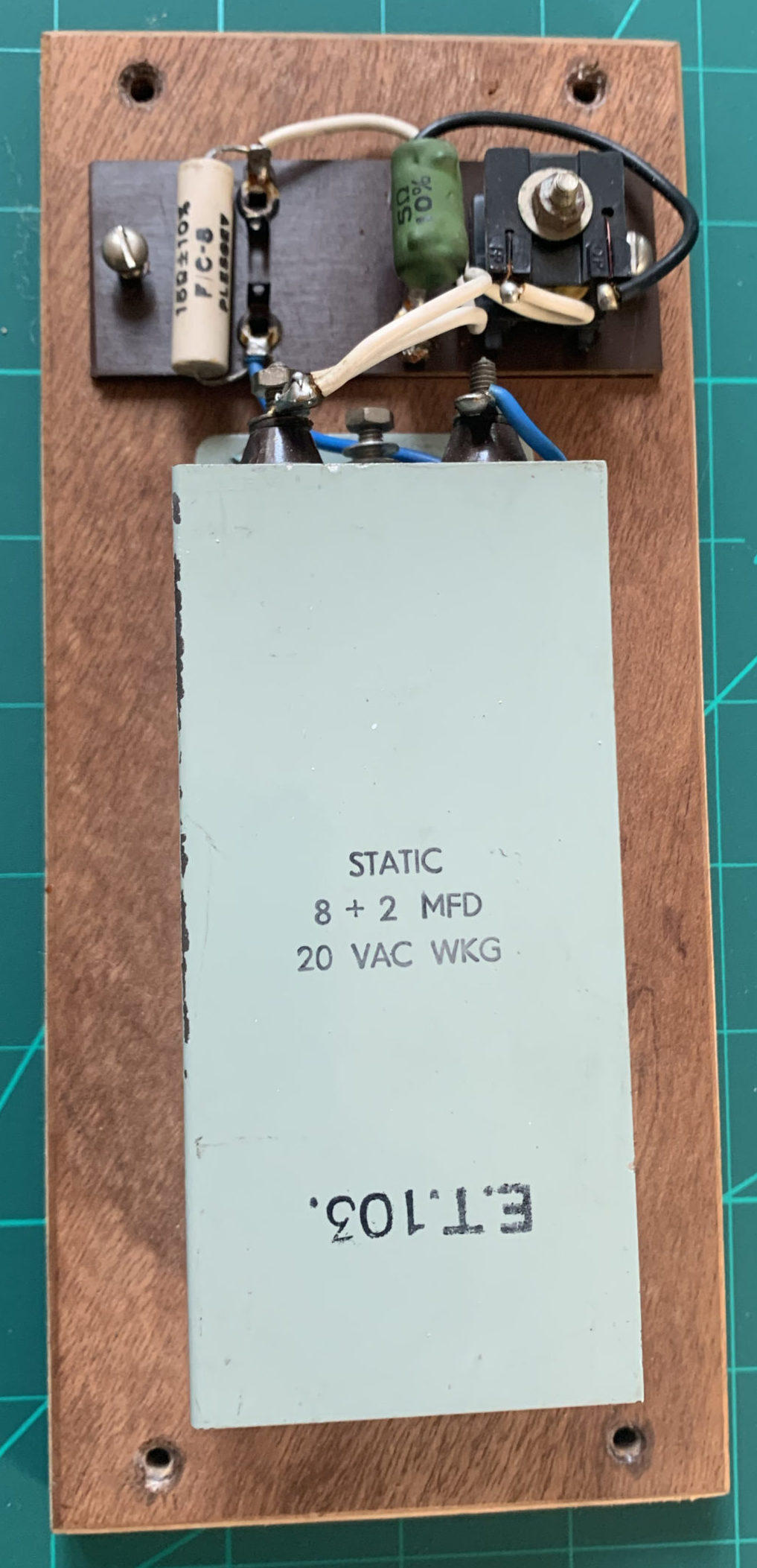
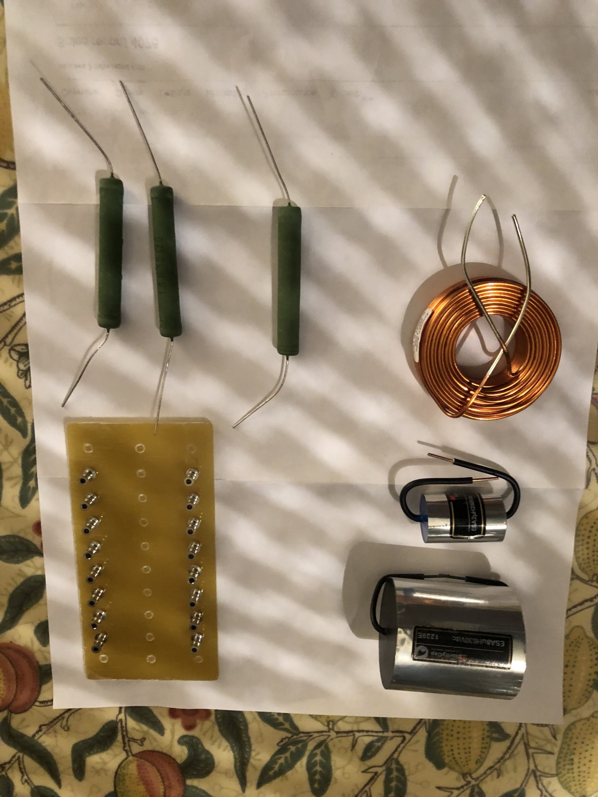
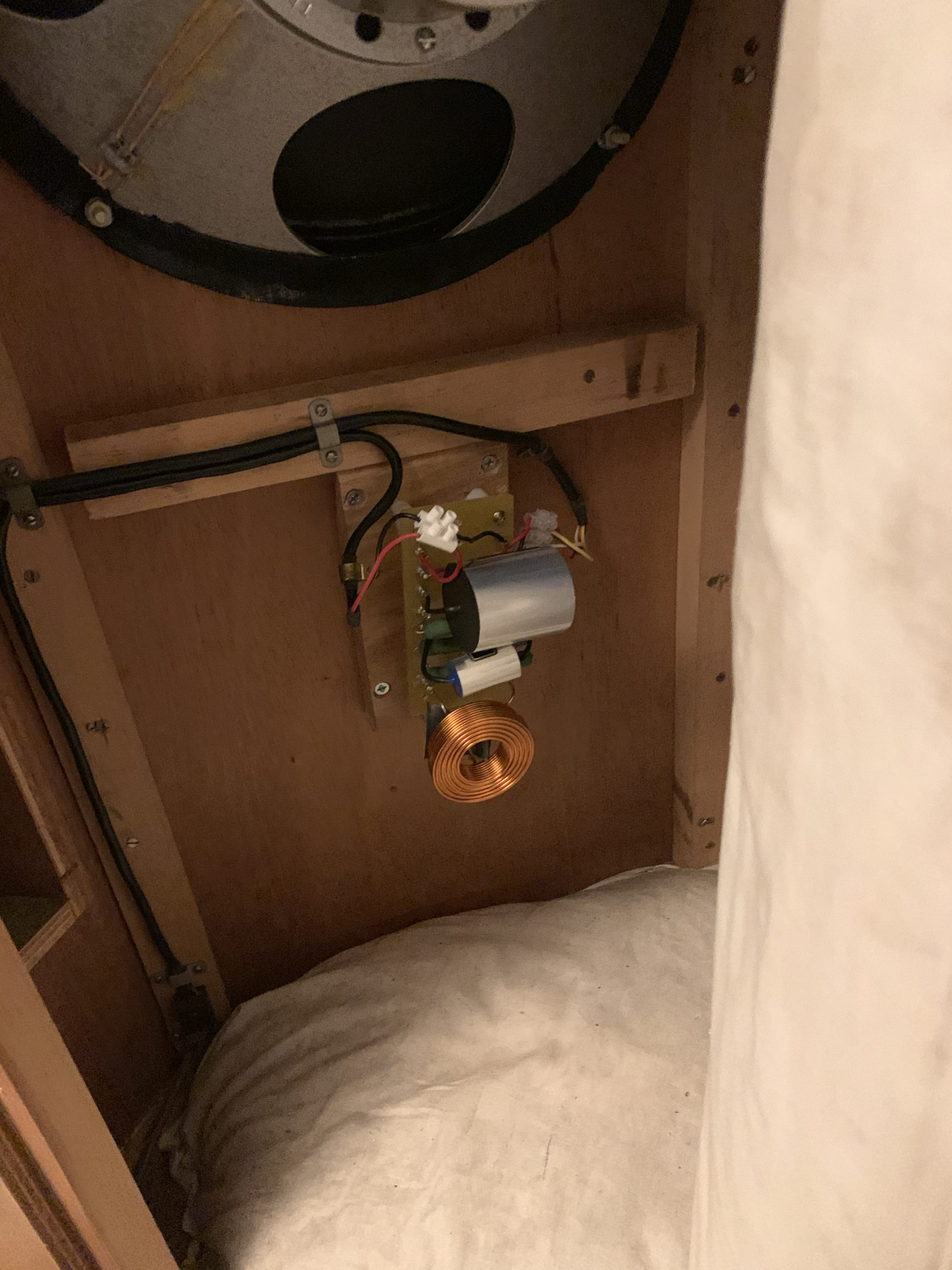
(Yes, I l know it’s a different version from the main image – but I said I have a few of these!!)


I said I don’t do this for a living!  Sometimes the patio furniture becomes your workstation on a sunny day during ‘lockdown’.

3 single core braided 22AWG, adhesive copper tape covered for a shield (and then later covered in insulation tape)


The Battery Box

Not that tricky.  

Bought a very inexpensive pine trinket  box on the  ‘bay.  (By the time I’d stained it, varnished and waxed it, it would probably  have been cheaper to buy a pre-made diamond encrusted box but that’s not really the point).

Two 12v SLA  batteries .  And a charger  . 

My cunning plan was the box would either charge the batteries (in parallel) or power the phono stage (with +12v/0v/-12v).  But given the capacity of the SLAs, it didn’t need to do both at the same time.

So even I managed to work out that I’d need a  4P3T switch, some sockets – my GX12s and power-in from the charger, and some cable. 

The charger had a couple of croc clips to charge the battery and that wasn’t going to work.  So I broke into the charger (literally – somewhat destructively as it was so cheap it was all glued together) and soldered a replacement cord with DC barrel pin from my collection of old wall warts that matched the barrel socket I took out of the phono stage…


It’s all a bit messy and there is some permanent damage but since it was going to sit on the floor anyway – I’m happy enough.


So here is what’s needed circuit wise:

Essentially, the batteries connect to the four terminals of the ‘OFF’ setting of the switch.  Then, thrown ‘right’ (as you look at the diagram), the switch connects ‘-‘ and ‘+’ to create the common 0v, and the left battery’s ‘+’ terminal forms +12v and the right battery’s ‘-‘ terminal forms -12v.

When charging, the switch has a couple of jumpers on the ‘left throw’ (again as you view it from the diagram) that place the batteries in parallel.  

In this way, there is no danger of the circuits ‘crossing’.

(You might read some stuff about not charging batteries in parallel.  They are probably, right, but it possibly won’t end badly. YMMV.   I guess the advice is – Don’t just follow blindly what some guy on the Internet says, especially when he admits to not being an expert at this…)

Assembling the Box (and supply cable)

Basically, you need a couple of holes for the in/out, and one for the toggle switch.  (And if you like, add a couple of status LEDs across the in & out (with appropriate resistors) to give some visualisation of the box’s state.  (i.e. charging or suppling).

When you wire up the connecting cable it’s obviously helpful if essential you maintain the pin positions!
I used screened  4 core cable (because I couldn’t find 3 core).
The female connectors on the cable screw satisfyingly onto their male counterparts on both boxes.
In hindsight, the silicone 18AWG connecting cables were tricky to solder to the little switch and I probably should have used single core 22AWG throughout (I was concerned I couldn’t crimp the 22AWG for the battery connectors but since I ended up using 22AWG for the GX12 as I couldn’t get stranded 18AWG to solder to the small legs, with a couple of connecting blocks to connect to the already soldered switch, I would have saved myself time and effort swearing by using the thiner hook-up wire.

The results

A/B testing phono stage with (temporarily sited) Hi Fi

It’s hard to A/B something when you’ve hacked A to pieces, but I’m pretty sure it’s sounds less hissy now at high volume, needle raised.  (Even though it was really quiet before).

[EDIT: I’ve A/B’ed it against the Rialto – it’s way quieter  – needle up, same phono stage gain, same pre-amp settings. Very happy!]

[Btw – I suspect my original issue with the Muffsy was the AC/AC adapter; I bought a cheap one rather than the one ‘Muffsy’ recommended – go figure!]

I’ve not used it for long enough to comment on battery life (not that that matters with the always-available charger. Nor whether, if the batteries have slightly different characteristics (which they will), there is any issue with either charging or with the phono stage because of voltage variations on the separate rails. (although the PSU it replaced had slight variations anyway presumably due to the Resistor and Cap components not being 100% matched).

What I did think, after the fact, is that since my Rothwell Rialto uses 24v DC from a wall-wart,  I could have incorporated this as an option by placing the batteries in series through another switch option.  I might have a think about that as a ‘future upgrade’, and how I could ensure ‘off’ before ‘on’ as I cycle between options.  If I can’t do it passively, I could always use an Arduino and Relay Board….

Restoring an Anglepoise 90

Restoring an Anglepoise 90

“When I was a kid, my great aunts had an original black Anglepoise.   Now the Anglepoise has become iconic and synonymous with Pixar “

But back then, it was just solid utilitarian British engineering!

Being older, I now realise it was a model 1227.  They still make these!

Unfortunately, I have no idea where the lamp ended up.  But, I was clearing out my parent’s house and found it’s younger sibling – the Anglepoise 90.  It’s not got the same seminal square pyramidic base, and it was painted in ’70’s light green.


And it was paint scarred.

So I thought I’d ‘restore’ it.  My idea was to sand it down and polish it to a mirror finish since it’s (mostly) Aluminium.

Unfortunately I didn’t really do any ‘before’ pictures.  

Also, I didn’t succeed in the mirror-finish.  Transpires I didn’t have either the equipment or patience or both to complete that! 

It does look pretty cool though, in a polished-ish, burnished final state.

And I did complement it with a red silk braided cord that is quite striking.

The ‘restore’

I disassembled the lamp. I did take a couple of pictures for reference (not enough as it transpires but more on that later).

Then I used paint stripper and rubbed it down progressively using finer grit wet n dry – I probably used about 8 grades, from 240 including 1500, 2000 and finishing on 3000.

I then bought some polishing mops for both my Bosch GRO 12V (basically a ‘Dremel’ like multitool) and my 18V Bosch drill, along with various jewellers polishing compounds.

Long story short, and possibly it was just lack of patience, but I figured I was never going to get a mirror finish using the polishing mops and doing it hand-held.

So I changed tack and convinced myself I’d be happy with the a more rustically burnished finish.  

(In truth, I really like it now).

I even decided to leave some traces of the old paint on a the swivel mount….

Reassembly

I bought a length of red silk covered braided 3 core flex.

My Anglepoise 90 was double insulated, but you don’t seem to be able to buy two core braided, so for good measure I decided to earth the lamp too.  I basically connected the earth core to a screw on the lower articulated element and checked continuity on the other metal components too.  This then meant ‘only’ feeding two twisted cores through the inner supports.

One very tricky part of the reassembly – the lower inner support that holds the cable on its run up to the lamp holder contains (in my version) a plastic insert designed to securely hold the flat, double insulated original flex.  I couldn’t for the life of me get this out, and I couldn’t get the two strands of the braid up it either.

The only way I managed was to ‘burn it out’ using an old 8W pencil thin soldering iron.  It cleaned up afterwards, but I’d rather not have done it that way.

I’d left a considerable time between disassembly and reassembly – probably three months, as other stuff got in the way. So I’ll admit to having been a bit puzzled as to some of the pieces on reassembly!  Fortunately, I was able to look on eBay where there are loads for sale and some good people had taken sufficient pictures to help me work through what I should have done it the first place.  Many thanks!

The resulting lamp looks good so another pleasing ‘project’ completed!