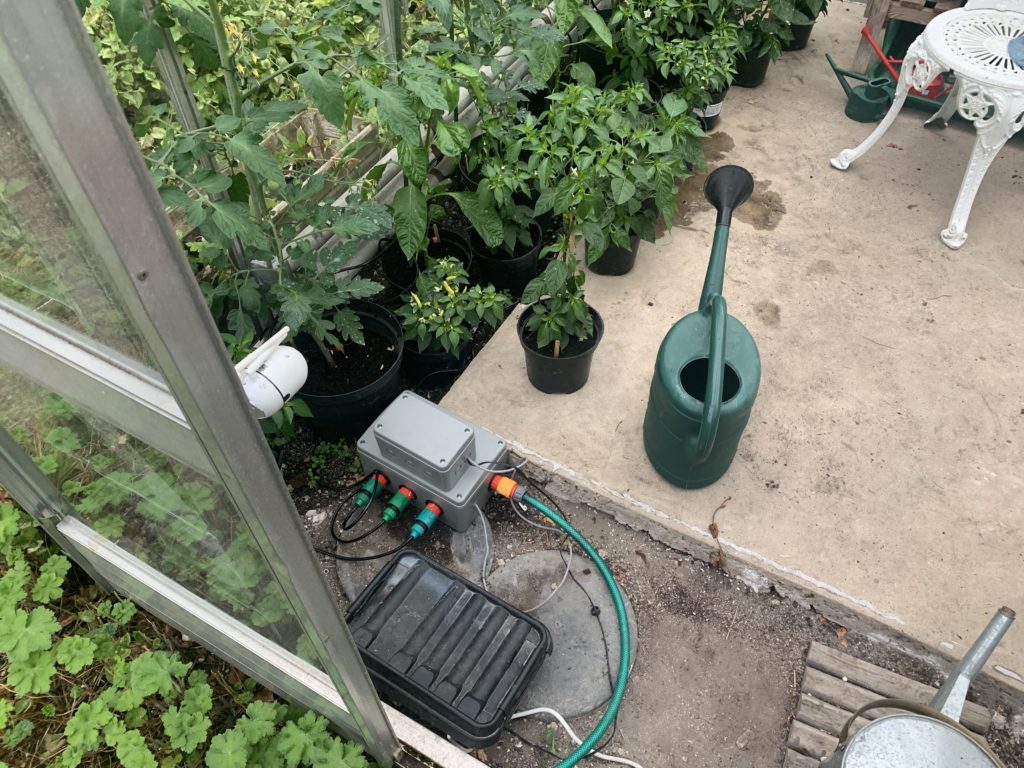
“Timer-based Irrigation Valves with Internet Control.”
This is the latest variant of a project I started last year which used a Raspberry Pi and Homekit bridge software to control greenhouse irrigation. The solution worked well, but the software was a clever adaptation of a Java-based HomeKit bridge developed by a colleague. In essence – way above my technical pay-grade.
This year I fancied adding another bank of valves, so looked around for a means to do this myself!
I happened upon the Sonoff 4CH Pro R2. This nifty device basically has 4 independently controllable latching relays, Wifi connectivity, phone app control and can be AC Mains or 5-12V DC powered.
Of particularly note about the Sonoff range is that they are based on the ESP2866 chip and that there is a strong community behind an alternative firmware called Tasmota and the Sonoff devices either directly support the ‘DIY’ flashing of the firmware or they are pretty hackable – depending on the device.
Tasmota provides extensive support for controlling the devices over various protocols including MQTT and offers great integration capabilities to Home Automation solutions such as OpenHAB which has been ‘on the list’ of things to do…
Step 1 though, as described in this post, was to get the valves up and running using the Sonoff app.
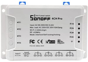
The Bill of Materials
This is not a particular cheap build – but something with the same capability available commercially such as the Gardena Watering Valve Box V3, with three solenoid valves would set you back about GBP 200-250 – without timer or connectivity.
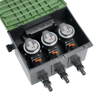
This is what I used:
Sonoff 4Ch Pro R2 as above- the Pro is needed as it has the 12DC input (as well as 433 radio control as an added extra..)
Some Cat 5 cable for connecting the Sonoff enclosure to Valve enclosure
2 enclosures – one for the Sonoff and one for the Valve enclosure. Note: these boxes are IP55, which is ‘low pressure jets from all angles’. If you want something more robust weather-wise, go for a IPx6. (The enclosure for the Sonoff is *just* too small internally because of the screw mounts. It means trimming the corners of the Sonoff – it does have mounting lugs so space to do this but if you don’t want to do that, source a bigger enclosure)
3 12V Solenoid Valves – these seem great value at under GBP 14 each
4 Garden Hose Tap adapters – best to get as good quality as you can. Mine were pretty budget.
Plastic piping: 1 x BLK PP Plug Thread 1/2 (SKU 350390), 3 x BLK PP Tee Thread 1/2 (SKU 350268), 3 x BLK PP Nipple Thread 1/2 (SKU 350299), 4 x BLK PP Reducing Socket M x F Thread 3/4″ x 1/2 (SKU 350341) – all from here. (Pipestock’s postage charge is quite chunky but the service and speed of delivery is very good).
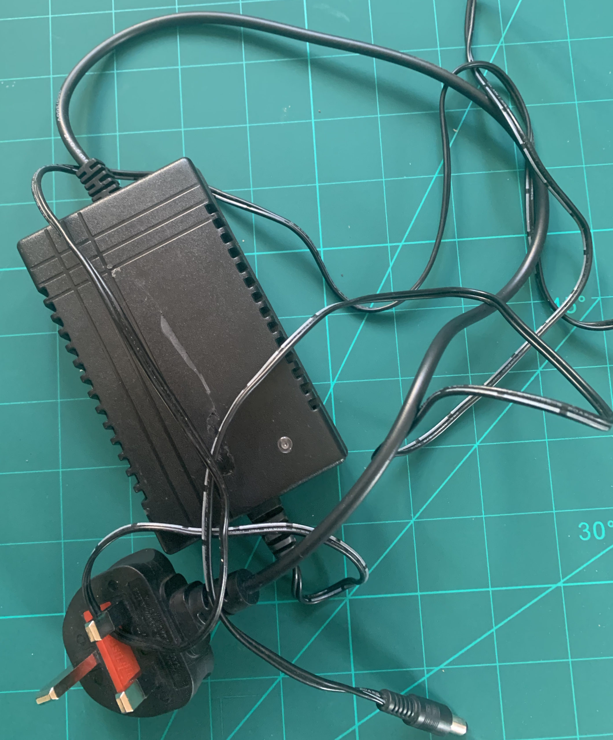
An old 12VDC 2A wall wart I had kicking around (mine had a 90 degree connector – this may be important for clearance in the enclosure if you go for the same enclosure I did)
A rough total cost including shipping, where applicable, would be about GBP 110-115.
The Build
The ‘plumbing’ part is pretty straight-forward.
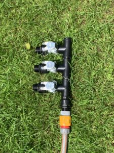
The approach I found to work well was to create three sub-assemblies of the Solenoids pairing each with a T-connector and reducing connector:
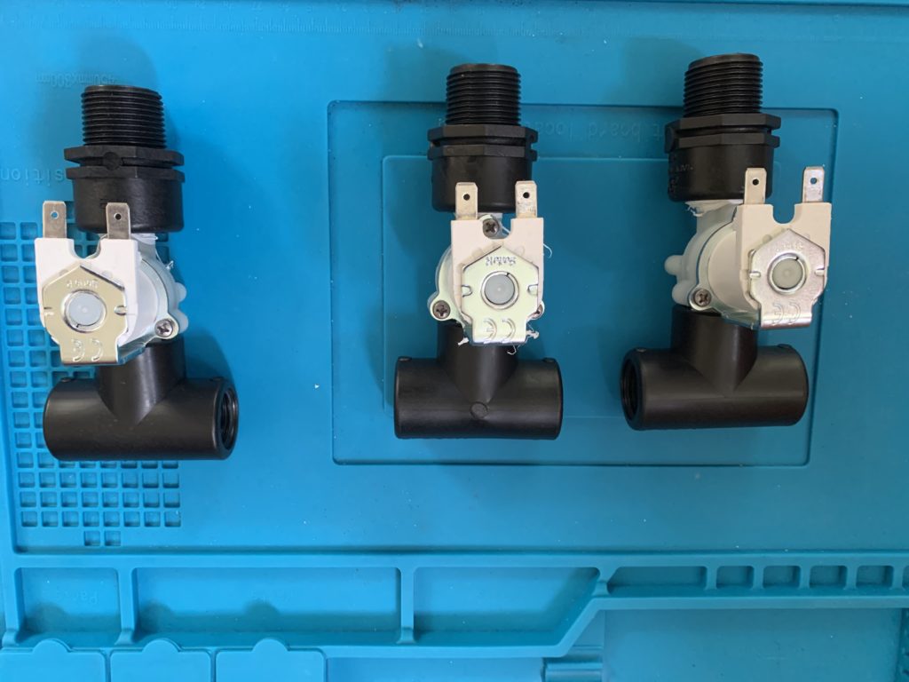
Your valves are likely to be ‘one-way’ – you may see a flow arrow on the underside of the solenoid or check the spec – the site I got mine from had the spec in PDF form. Make sure everything is (water) tight and use teflon tape if so inclined.
When the valves are joined you will not find it easy to tighten the sub-assemblies further.
Now join the sub-assemblies with the parts curiously called the threaded nipples, together with the threaded plug one end and another reducing part the other:
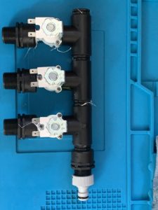
Now would be a good time to do a leak test:
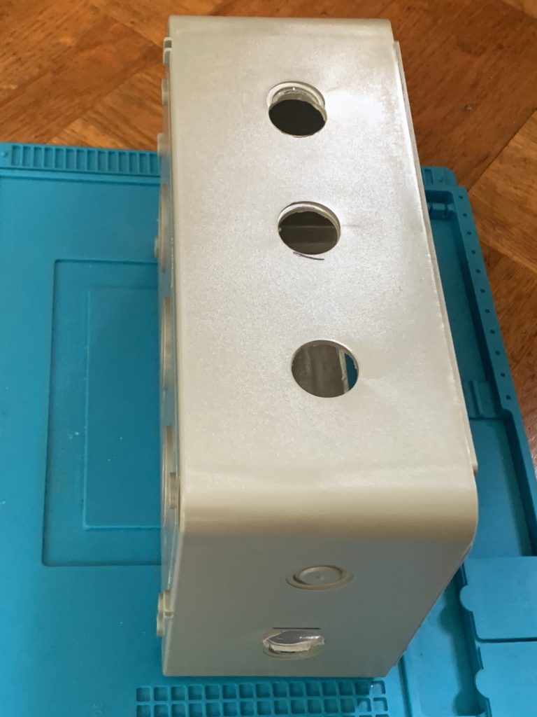
Drilling the enclosure requires some skilful measurement – it’s tempting to use the cut-outs as a guide but they are not an exact spacing in relation to the valve assembly – or at least in my combination that is what I found. Use one cut-out as the starting point and measure the other two. Measure for the inlet and drill. (I used a flat wood bit because that’s what I had. You have the choice of using a 22mm in which case you may need to sand out the cutouts by a half mill or so or use a 25mm and accept a you will have a ‘gap’ around the valve threads on exit. I did the ‘hard’ or rather time-consuming way – using a 22mm drill bit).
You should have something like this:
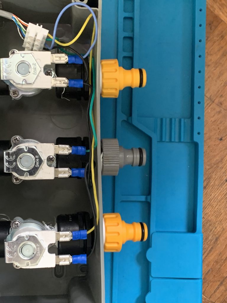
You now need to ‘wrangle’ the solenoid valve assembly inside the enclosure (having first removed the hose tap connectors you may have used for the leak test). Fortunately, there is a lot of flex in the enclosure (at least the one I used). With the hose connectors attached the valve assembly is ‘secured’ within the enclosure. You could provide additional support to the assembly if you wish. It seems fine without….
Now for the wiring. I spade-terminated a length of cable for the +ve supply of each solenoid and ran that to a connector strip. The -ve connection I just daisy-chained to each solenoid and also back into the connector strip.
Then whatever length of cat5 you want (from one enclosure to the other). I doubled the twisted pairs so three pairs are supply to respective solenoids and the forth pair is common.
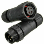
I ran the cat5 out through a drilled hole for expediency. Ultimately some panel mount and wired IP68 4 pin connectors like these would be a nice touch but I didn’t have the time to order them….
Finally, the Sonoff unit is installed in the second enclosure. Annoyingly, the internal measurements of the enclosure weren’t available and it meant trimming the corners of the Sonoff with a multi-tool. Not a problem for me but you may want to source a bigger enclosure if it bothers you doing this.
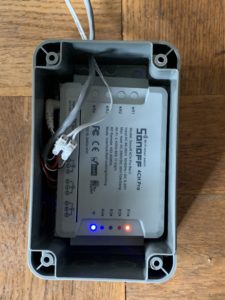
The relays on the Sonoff do not supply power, so you basically need to have power going to the ‘com’ tab of each relay and then each solenoid wired to a respective normally open tab of a relay. Thus when the relay is closed, 12V flows to the solenoid.
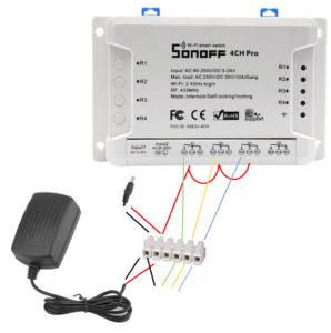
There is probably a much more elegant way to wire this but essentially I cut the connector off the wall wart 12V supply and put both ends (+ve and -ve) into a connector block. I connected +ve to each of the ‘common’ tabs of three of the relays. So essentially 12V power goes to each terminal and also powers the Sonoff through the 12VDC input.
Then I wired the NO (normally open) terminal of three of the relays to the three pairs of cat 5 that correspond to the +ve supply of each of the solenoids.
I’m not sure this dodgy ‘circuit diagram’ helps but you’ll figure it out…:
The App
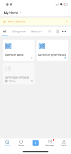
The Sonoff ‘comes’ with iPhone and Android app support – the ‘ewelink’ app. It’s OK … in that it’s not rubbish and it works reliably. You can set schedules and see status of the relays:


The Result
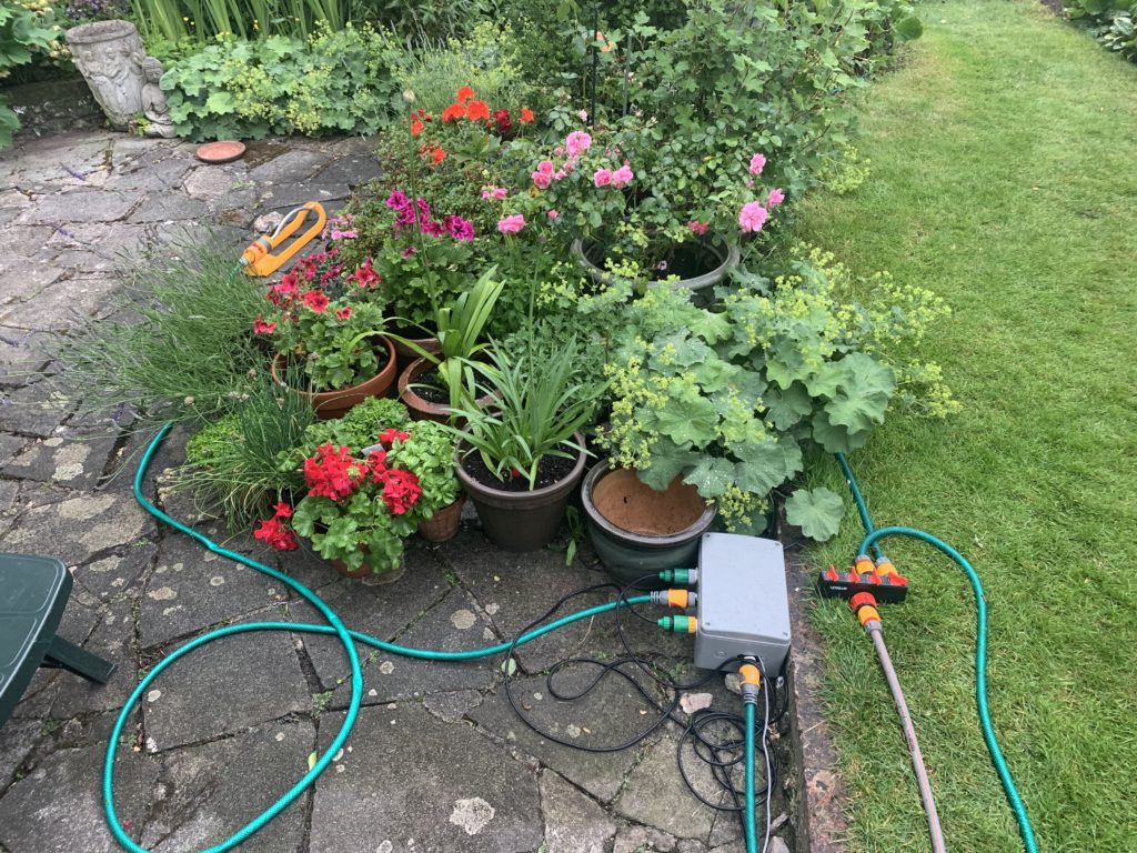
Works as expected! Reliable. No leakage.
Liked it so much I built 2.
The Future
There is more to come hopefully.
First, flash the firmware with Tasmota. This offers some connectivity benefits to OpenHAB which I plan to implement, and would give HomeKit integration and decent rules-based behaviour and data capture and monitoring.
Add some sensors. With Tasmota, the Sonoff’s I2C pins can be exploited for sensors. I’ve got some DS18B20 2 wire temperature sensors. I plan to get some I2C moisture sensors too. Maybe also some rain sensors.
That way, the solution can provide feedback on actual moisture levels and I can automate the schedules based on this, and with the outside unit, compensate for wet days.
Probably also plan to build one or two additional units for the ‘top garden’!
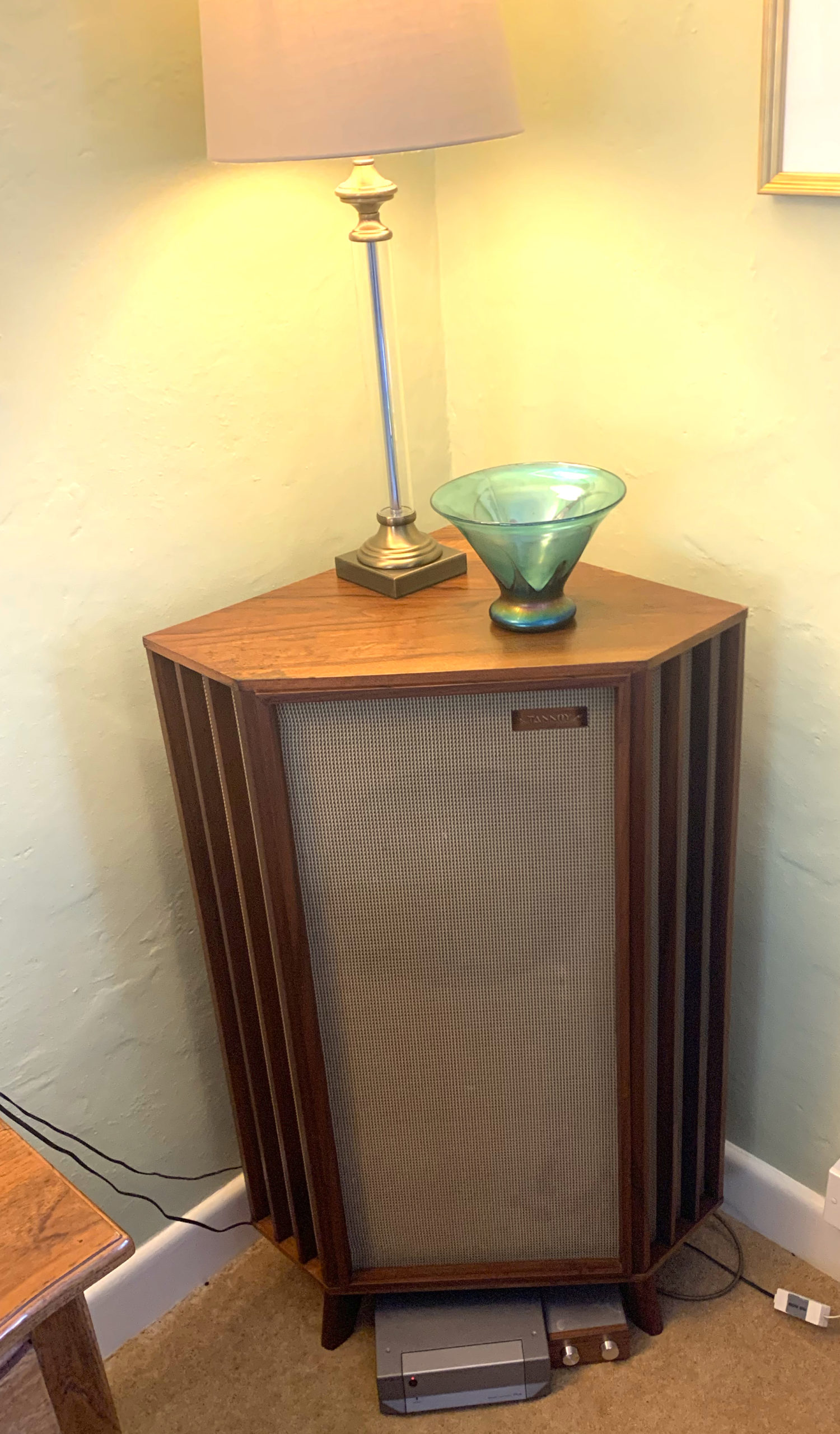 Tannoy 12″ Silver monitor in Canterbury Enclosure
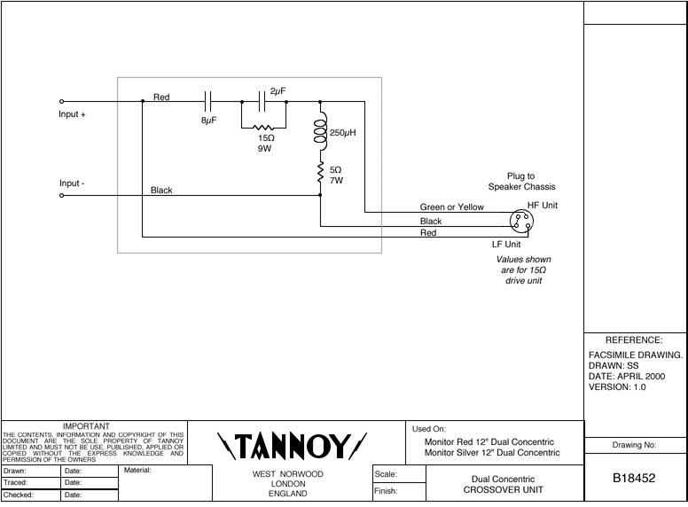
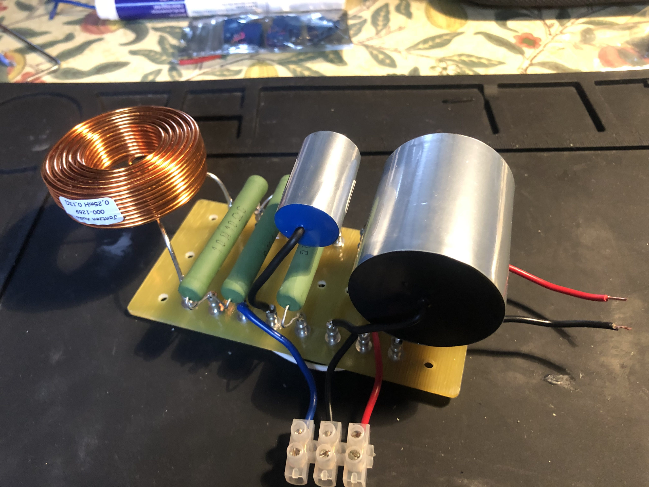
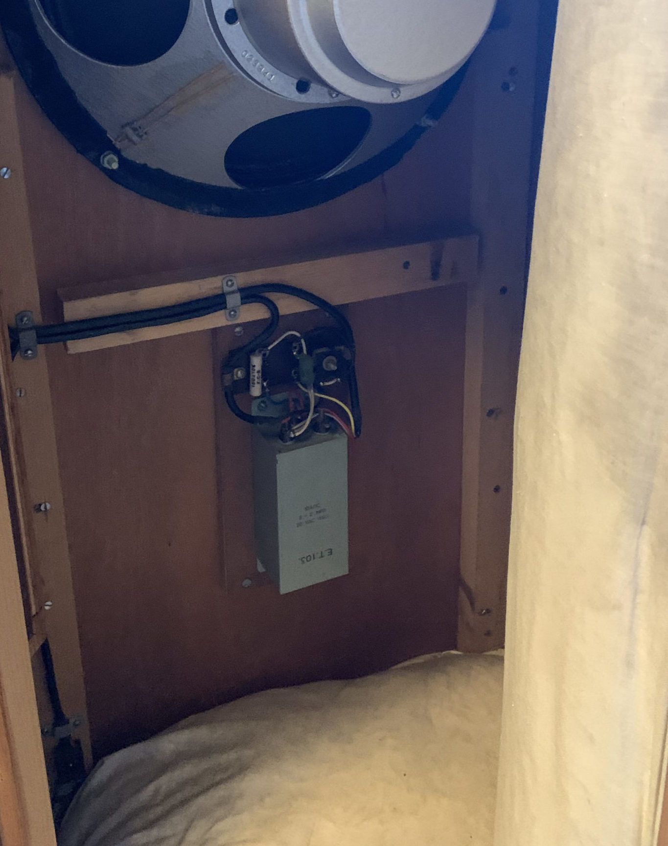
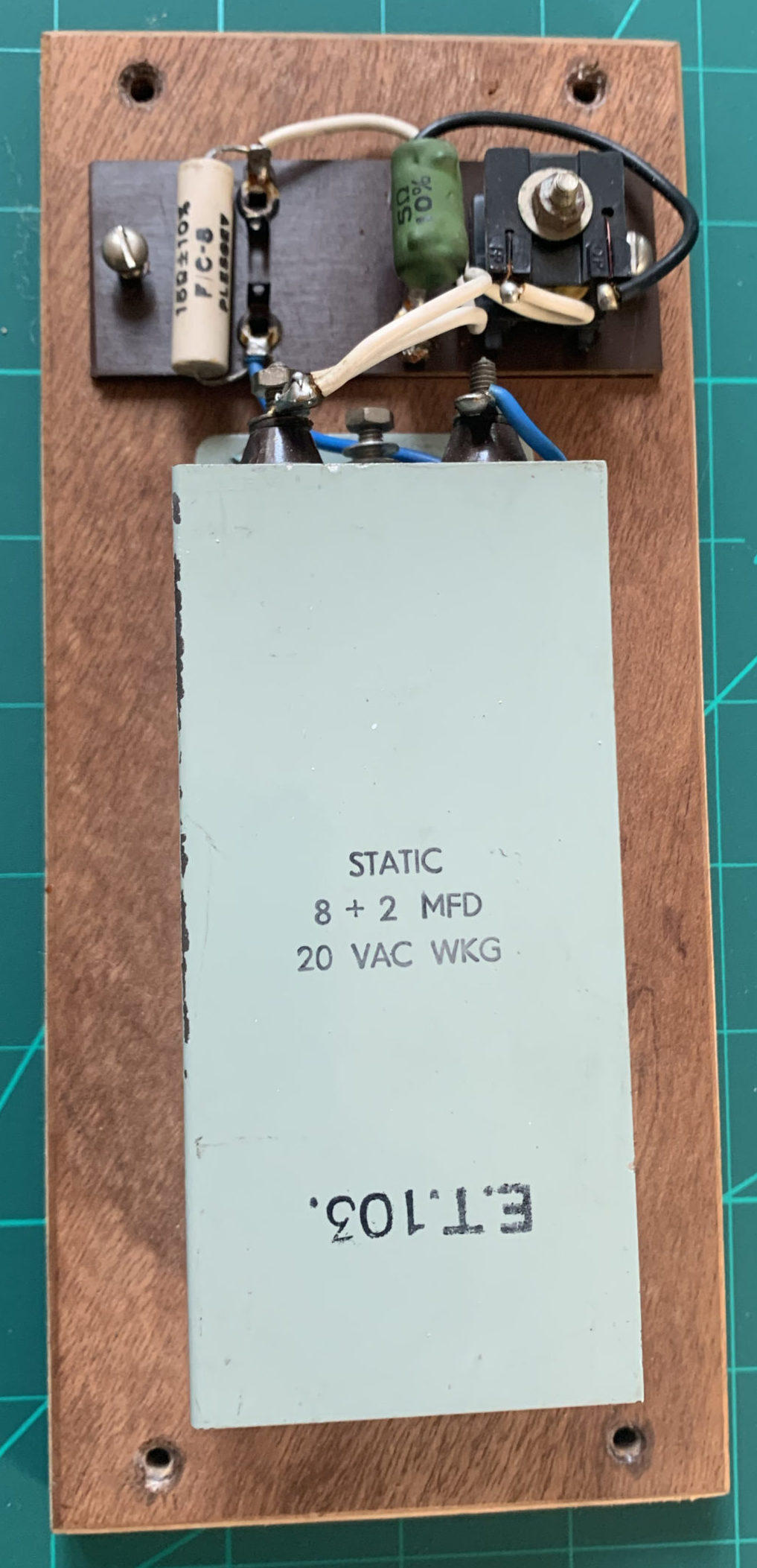
 (Yes, I l know it’s a different version from the main image – but I said I have a few of these!!)